Introduction to Phase-locked Loop
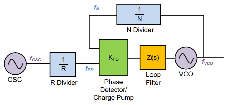
The phase-locked loop (PLL) is an electronic module that generates a signal with a stable frequency. The idea is to introduce a feedback loop that calculates the instantaneous phase (or frequency) drift of an oscillator and corrects it. The basic architecture of a PLL is depicted in Figure 1.

The PLL comprises a voltage-controlled oscillator (VCO), a reference oscillator (OSC), and a feedback loop that stabilizes the frequency of the VCO. The OSC provides a low-noise (stable frequency) reference signal that typically has a fixed frequency, denoted as $f_{\rm OSC}$. The VCO, in contrast, has a frequency depending on the bias voltage and a relatively high phase noise. The function of the PLL is to stabilize the frequency of the VCO to a level comparable to that of the OSC.
The output of the OSC is down-converted by the R divider to $f_{\rm PD} = f_{\rm OSC} / R$. For an integer divider, $R$ takes a positive integer; for a fractional divider, $R$ is a fractional number. Similarly, the output of the VCO is down-converted by the N divider to $f_{\rm N} = f_{\rm VCO} / N$. The phase detector/charge pump then calculates the frequency difference between $f_{\rm PD}$ and $f_{\rm N}$ and generates a periodic pulsed current signal, whose amplitude and duty cycle depend on the frequency difference. This pulsed current signal is then fed to a low-pass loop filter and converted to a sine-wave signal, which is in turn fed to the VCO for frequency correction.
In the steady state of the PLL, the correction signal should be zero, which means $f_{\rm N} = f_{\rm PD}$. In this case, the frequency of the VCO must be:
$$ f_{\rm VCO} = \frac{N}{R}f_{\rm OSC}. $$
The output frequency of the PLL can be specified by adjusting the ratio between $N$ and $R$. Note that this output frequency remains unchanged if we increase $N$ and $R$ proportionally. This gives us a degree of freedom for choosing the frequency division factors. In practice, however, both division factors should be as low as possible for better frequency stability (or lower noise level). At the same time, these division factors should not be too low; otherwise, $f_{\rm N}$ and $f_{\rm PD}$ may exceed the bandwidth of the phase detector/charge pump.
Applications of Phase-locked Loop
Frequency synthesis is an important application of PLL. Frequency synthesis refers to the task of generating a low-noise signal of a specified frequency. This can be done by adjusting the two frequency division factors $N$ and $R$ of a PLL. It is worth mentioning that PLL enables the generation of signals with frequencies much higher than that of the OSC (usually made of a quartz crystal and has a fixed oscillation frequency of 10-100 MHz), enabling us to obtain low-noise millimeter signals with frequencies up to tens of GHz.
Clock recovery is another valuable application of PLL. For a radio receiver to sample and readout a provided signal, it should have a local oscillator that matches the given signal in frequency. However, the local oscillator may drift in frequency due to various perturbations, and we need to synchronize this oscillator with the period of the arrived signal. This synchronization process is known as clock recovery and can be accomplished by replacing the OSC in a PLL with the arrived signal to lock VCO (similar to injection locking). This scheme has been playing an important role in today’s radio receivers and optical transceivers.
Reference
- Banerjee, D. (2006). PLL performance, simulation and design. Dog Ear Publishing.